A client recently asked us whether vacuum may be a problem for her piping system. She was aware that the piping codes pointed to the external pressure check in ASME VIII Division 1.
I won’t make this out to be a simple topic and indeed there is still ongoing research in the area. But for most piping systems at atmospheric pressure, there is a faster and easier way to check for vacuum resistance.
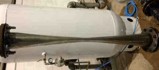
Long cylinders
The Div. 1 method is based on work from the 19th and early-to-mid 20th centuries. The basic equation for collapse pressure of a long cylinder is as follows [1] –
In this equation, the theoretical collapse pressure is divided by 3. This is not a true safety factor, as out of roundness leads to collapse at lower than theoretical values. ASME VIII limits out-of-roundness to 1%, which is said to achieve a collapse pressure of 80% or more of theoretical, i.e. the safety factor is 2.4 or more.
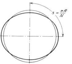
The collapse shape for long cylinders is as shown in the image below. N is the number of lobes or peaks, which is two for a long cylinder (i.e. results in an oval collapse shape).
For steel at ambient temperature with Young’s modulus approximately 205GPa and poisson’s ratio 0.3 we get the following (for p in units of MPa):
For pressure in ksi, you would change the above multiplier to 21750.
At atmospheric pressure and sea level, p =0.101MPa (0.0146ksi), which corresponds to D/t=114. For stainless steel, the D/t value is about 112. For a more flexible material like titanium, the figure is 94. With higher temperatures we get a lower Young’s modulus so we round these down. So as a rule of thumb, we should be concerned at D/t values of 90 for titanium and 105 for ferrous materials. The D/t ratio of Sch10S piping is about 95, which is OK for full vacuum in stainless steel but not in titanium.
We would subtract corrosion allowance and welded pipe mill tolerance from the thickness for this assessment. It would be overly conservative to consider a 12.5% (seamless pipe) mill tolerance, as this is usually associated with short arcs of reduced wall thickness.
Critical length
An approximation to the number of lobes in the buckled shape is given in reference 1. For a metallic cylinder with poisson’s ratio taken as 0.3, this gives:
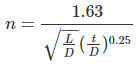
Obviously, the number of lobes must be an integer whereas this formula gives a real number. Reverse engineering the chart in reference 1, with this simplified formula the dividing point between 2 and 3 lobes corresponds to n ~ 2.33. Thus we get:
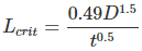
If your pipe / vessel is shorter than this, or it has vacuum rings spaced at lengths below Lcrit, its vacuum capacity will be greater than predicted by earlier equations. To actually calculate its capacity you would need to apply the ASME VIII or similar methods.
Note that for lengths above the critical length, the buckling pressure is effectively constant with increasing length.
Accounting for additional ovality
The factor of 3 in these formulae assumes an out-of roundness of 1% as per ASME VIII and most ASTM pipes. However, specifications API 5L and ASTM A53 permit 2% out of roundness for some piping. For these pipes the external pressure capacity should be further reduced. There are not many sources on this topic, but I will highlight those I’m aware of here.
The easiest method I know of is from reference 2 (and is a simplification of work in reference 3). We have the following equation for modified elastic buckling pressure p’el (with Poisson’s ratio taken as 0.3). As this formula directly accounts for ovality (as opposed to the earlier theoretical equation), we have applied a dividing factor of 2.5 rather than 3.
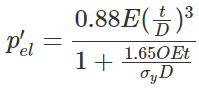
where out of roundness or ovality at a given cross-section is defined as:
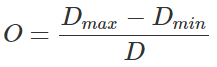
This method accounts for the increased stress due to local bending of the imperfect shell wall, hence the use of yield stress in the denominator. I suggest using it for ovalities greater than 1% – note it is only to be used for cylinders above the critical length. It is not intended to justify increased external pressure capacity at 1% ovality (which it would predict for yield stress greater than 0.0825Et/D), although the credit for increasing yield is moderate.
The second method I will highlight is from DNVGL-ST-F101 [4] (and itself originates from BS8010). Based on the classic hoop stress formula, define yield pressure:

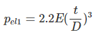
Define classical elastic buckling pressure pel1 (without safety factor); with poissons=0.3 we get:
Then the relationship between collapse pressure pc, classical elastic and yield pressures is:
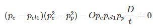
Although there is an analytical solution for this formula, it requires many steps and it is easier to solve iteratively for pc, and then apply a safety factor (I suggest 2.5).
These formulae typically show a reduction in capacity of less than 20% when going from 1% to 2% ovality.
Accounting for external loads
For most piping, external loads in combination with vacuum will have modest effect, which is sufficiently compensated for by the safety margins applied. We should be careful for long vertical lines, high temperature lines and pressures above atmospheric.
Methods are available to evaluate these effects including in DNVGL-ST-F101, ASME VIII Division 2 and Russian GOST 32288. This is perhaps a topic for another time.
Collapse of short / thick cylinders
Analysis of shorter cylinders (including pipe with vacuum rings) is more complex, hence the need for the ASME vacuum chart and similar methods. We will go through the ASME method and potential simplifications that can be applied in a later post.
To be notified of future articles and resources added to this site, subscribe to our mailing list below.
References
- Collapse by Instability of Thin Cylindrical Shells Under External Pressure, Windenburg & Trilling, 1934
- Pressure Vessel Design, Annaratone, 2007
- A Study of the Collapsing Pressure of Thin-walled Cylinders, Sturm, 1941
- DNVGL-ST-F101 (2017) Submarine pipeline systems
Martin helps clients keep on top of their pressure piping and equipment integrity issues via stress analysis, FEA and fitness for service. He is the author of various articles, an ASME paper and software including the Salad post-processor for CAESAR II and web apps on this site. In a former life he played whizzbang lead guitar, but now he just plays old albums..