There are at least three recognised methods for assessment of branch intersections. These are most often applied to fabricated connections on pressure vessels and piping rather than welding tees.
Welding tees to ASME B16.9 are normally qualified by vendor burst tests, but that doesn’t help if you need to assess a corroded or eroded fitting, or you want to check up on a purchased fitting. (One paper from 2014, PVP2014-28265, found non-compliant fittings that failed below their required burst pressures). Another standard, EN10253, gives recommended fitting thicknesses and calculation methods.
For pressure calculation of welding tees, we’ll cover and compare three Code methods and another approach from a recent research paper. The methods considered are as follows:
| No. | Method | Reference(s) |
|---|---|---|
| 1 | Area Replacement | ASME B31.3, ASME VIII Div. 1, PVP2014-28265 |
| 2 | Pressure-Area | EN13445, EN13480, ASME VIII Div 2, EN10253 |
| 3 | Local Stress | PD 5500 |
| 4 | Local Stress | PVT-17-1119 |
The area replacement method is perhaps the one most familiar to mechanical engineers. The area of pressure retaining wall removed must be replaced by sufficient thickness in the locally surrounding metal. It has not typically been used for welding tees, however a way to apply the method will be developed in this article.
The pressure-area method has its origin in Kellogg “Design of Piping Systems”. The concept is that pressure times the area of contained fluid must be equated by allowable stress times the area of metal. It has been adopted in European codes such as EN13445-3, EN13480-3 and more recently in ASME VIII Division 2. Standard EN10253 for fittings includes examples of how to calculate adequacy of pressure containment.
The PD5500 method is based on research into local stresses at pressure vessel branches in the 1960’s.
The fourth method is essentially a local stress check in the tee crotch area. It is based on shell theory with an empirical correction to bring it in line with FEA results.
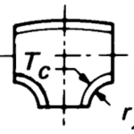
For most of these approaches, you need to know the crotch radius 


Area replacement method
In the B31 codes, this method is conventionally applied to fabricated intersections. It is also applied to extruded tees, however the approach is fairly awkward, involving fitment of rectangles into curved sections

The codes don’t show a method of assessing welding tees, however the curved profile of the welding tee does lend itself well to a simple calculation. This problem was addressed in an ASME paper from 2014, “Burst Tests of B16.9 Welded Tees.”, PVP2014-28265, in which an equation for thickness was given.

In the above, the first term represents A2, the second represents A4 (the crotch region), while A3 is conservatively set to zero. The factor K is from ASME B31.3 Cl. 304.3.4(e), and goes from 1 for full size intersections to 0.7 for small branches (Db/Dh<=0.15). This factor does not appear in the area-replacement formulae for fabricated tees, nor in the ASME VIII Div. 1 method.
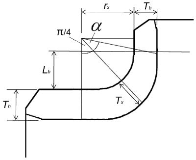
Eqn 1a provides a good start, but it was not really the main thrust of the paper. So let’s make this approach a little more rigorous via the following modifications –
- use the centreline radius of curvature to calculate length of reinforcement for A4
- split A4 into two regions – ‘header side’ (the first 45 degrees of the crotch) and ‘branch side’ (the remainder)
- reduce length of A2 so that it stops at the start of the crotch region
- limit reinforcement zones to B31.3 limits for extruded tees, but no further than the ends of the fitting (minus one times thickness for tapering)
- consider reinforcement in the branch, if within the limits (region A3)
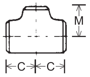
Setting reinforcement limits:


where C and M are as shown below:
Limiting angle 

This leads to the following form of the equation for the area replacement check.

This is based on 

For design, we might assume constant thickness throughout fitting (

We would then iterate until the value of N converges.
It should be noted that none of these versions of the area replacement method are specifically endorsed by any Code. At this stage I would also be wary of using a K-factor of less than one until proven adequate in this application.
General Issues with the Area replacement method*
- There is a lack of agreement concerning distances over which reinforcing material should be placed to be effective
- The rule is not based on quantitative assessment of peak stresses nor theoretical models
- Does not provide a uniform factor of safety over the full range of header/branch geometries. There is no consistent margin with respect to shakedown, distortion or fatigue.
- In thick wall equipment it may give excessively rigid designs (with attendant problems in welding for fabricated intersections)
* Ref. PD 6550 Part 2 Explanatory Supplement to BS5500:1988
Pressure-area method
The intersection is broken into 4 quadrants for assessment. The assessment is in accordance with equation 2:

Examining the formula, we can see that increasing diameter of the header or branch increases the pressure-area of the quadrant, necessitating a thicker wall. If we step back and consider it, it’s actually just a generalisation of the basic hoop stress formula. The following is for a cylinder; a similar approach could be taken to derive the equation for a sphere.

Per unit length:

or

The method differs slightly from the original Kellogg approach, which considered stress intensity by further adding half the pressure to the stress.
Formulae
As there are quite a number of equations involved in the actual calculation, they are not reproduced here. Instead refer to EN10253-2 Section A.5.2.
Limitations
- The wall thickness
and
apply to the whole perimeter of the run and the branch, respectively. At transitions between the run and the branch (crotch zone) the inside and outside surfaces shall merge smoothly.
- The minimum wall thickness at the branch
Issues with the Pressure – Area method
The issues with this method would appear to be similar to those of the area replacement method, namely
- There is no obvious universal law governing distances over which the reinforcing calculation should be made
- It is not based on quantitative assessment of peak stresses
- Does not provide a uniform factor of safety over the full range of header/branch geometries. There is no consistent margin with respect to shakedown, distortion or fatigue.
The EN method equations are not given in detail here. Refer to EN10253-2 Annex A for a full demonstration of the method.
PD5500
Section 3.5.4.3 of PD5500 contains a method for calculation of vessel nozzle connections by imposing a limit on local stress, based on the work of Leckie & Penny (1963). It makes the assumption of a right-angle intersection, ie there is no recognition of the effect of a radiused intersection.
To apply this method to welding tees, first select a value for 
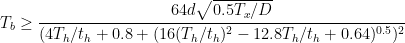
The equation should be iterated until it converges. Then a further check is made on
In these formulae, 

Issues with the PD5500 method
This method is simple and quick to apply, however it may not adequately consider the effect of fitting size – i.e. it could assume the reinforcement zone is larger than available in a pipe fitting.
PVT-17-1119
In this paper, shell theory is used to calculate a theoretical membrane stress in the tee crotch. The calculated stress overestimates the actual stress due to the reinforcing effect of the straight pipe and the rapidly changing curvature in this region. However, using an empirical equation, it is then adjusted to match quite well with stresses from finite element analysis. The equation is said to be typically 0 to 15% on the conservative side for the range of geometries considered.
Formulae
Although not overly complex, due to the number of equations and the need to apply numerical differentiation the method is not reproduced here.
Issues with PVT-17-1119 method
This approach has limitations in terms of geometry and thickness parameters due to the range of fittings considered in the research.
One interesting difference with this method is that a smaller crotch radius leads to higher local stress and an increase in wall thickness required. The pressure-area & area replacement methods both imply the opposite in terms of wall thickness required. Burst tests generally agree that a smaller crotch radius for an otherwise identical welding tee has greater capacity. While stresses may start off higher, the additional surrounding metal makes up for it as yielding progresses.
This demonstrates the shortcomings of elastic analysis methods when used for pressure containment of complex components. However, the local stress approach may be relevant when issues such as fatigue or stress corrosion cracking are of concern.
Brief Comparison of Methods
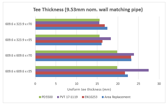
Required thicknesses were calculated by each method for four geometry variations (assuming constant thickness throughout each welding tee). The value of K was set to 1 for the area replacement calculations.
The notable outcome of comparison is the remarkable agreement between the pressure-area and area replacement approaches. However we have just considered a small sample of fittings, so we won’t make any firm conclusions here.
The PD5500 method consistently generated the thinnest or near-thinnest wall. This tends to confirm the possibility that some tee fittings have less reinforcement length than assumed for this equation (which is intended for vessels).
PVT-17-1119 results varied from less to more conservative, though it mostly leaned to the conservative side. For these calculations, local stresses were limited to 

Conclusion
At this point in time, the pressure-area method as given in EN10253-2 is the only fully codified approach for welding tees. The area replacement method demonstrated here seems to give similar results and the concept is familiar to most engineers, however its use with welding tees is not spelled out in codes. The method in PD5500 consistently produces the thinnest wall and may not adequately consider the effect of fitting dimensions. PVT-17-1119 tends to require thicker wall on average as it tries to keep the local membrane stresses within code limits and it has a typical error margin in the range of 0 to +15%.
Martin helps clients keep on top of their pressure piping and equipment integrity issues via stress analysis, FEA and fitness for service. He is the author of various articles, an ASME paper and software including the Salad post-processor for CAESAR II and web apps on this site. In a former life he played whizzbang lead guitar, but now he just plays old albums..
Great article!
Excellent article, very enlightening. I was wondering if you had the actual data of your last chart, i’m programming some calculation on tees but i can not find reliable data to compare results.
Great and in-depth explanation..