The example will create a model in NozzlePro using minimal user input (3 clicks and 4 numerical entries) to obtain useful information. This article will also highlight a somewhat controversial aspect of how the B31.3 code treats reducing tees (which is expected to change soon).
One reason for the popularity of NozzlePro is that specified maximum vessel nozzle loads are usually too conservative and are often based on legacy company specifications which were issued before modern finite element analysis was widely available. When it is impractical to keep piping loads on a vessel nozzle within specified values, qualification of the vessel nozzle using finite element analysis is often the preferred alternative. This situation arises frequently with vessels built to ASME VIII Division 1 which does not provide explicit rules and equations for qualifying vessel nozzles. It can also be used to obtain stress intensification factors (SIFs) for use in pipe stress calculations.
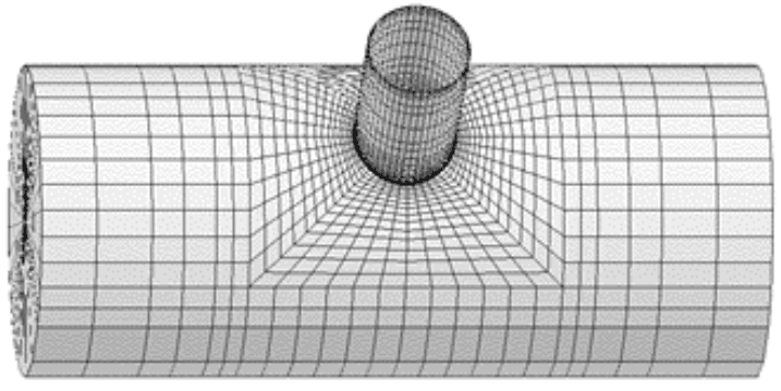
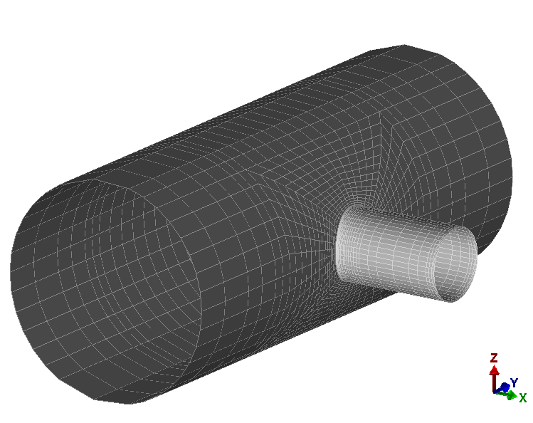
An unreinforced fabricated reducing tee (DN1800 x 600) is created with a total of 7 user inputs. Dimensions of the tee are:
Header/Run: OD = 1829 mm, WT = 16 mm
Branch: OD = 610 mm, WT = 13 mm
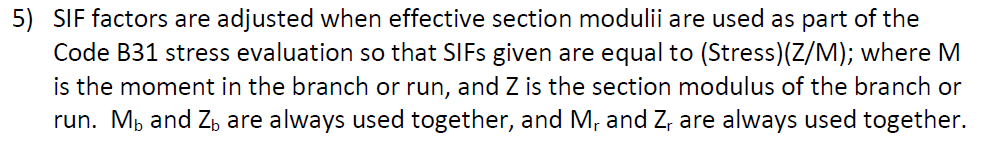
The D/t ratio of the header pipe is 114, it exceeds 100 and therefore outside the range of the stress intensification data in B31.3 Appendix D and B31J which state the validity has been demonstrated for D/t ≤ 100.
The template is very easy to use and only 7 actions to set up the model.
- Base Shell Type = Cylinder
- Nozzle / Attachment Type = Straight
- Set Units to SI (optional)
- Cylinder – OD (1829) and Wall Thickness (16)
- Nozzle Geometry – OD (610) and Wall Thickness (13)
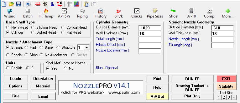
That’s 3 clicks required (base shell type, nozzle / attachment type, units). The default units are English so users in the USA, Liberia and Myanmar will get away with one less click 😉. 4 entries are required (cylinder OD and wall thickness, nozzle OD and wall thickness).
In total only 7 things that a user needs to tell NozzlePro before you can plot and run the model.
Note that no information has been entered regarding parameters such as pressure, mechanical loads, boundary conditions, mesh parameters, material properties, shell and nozzles lengths, axes orientation.
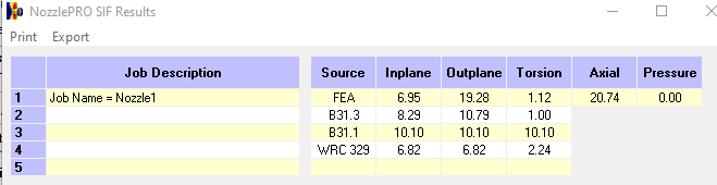
However, the model can be run to obtain some useful information – the SIFs and flexibilities. These could be used in beam type piping model. Notice for example how much higher the FEA calculated outplane SIF is compared to the standards B31.3 Appendix D SIF.
Good engineering practice when using any software is to verify output using a hand calculation. Doing this using the formulas provided under “Unreinforced fabricated tee” from Table D300 of B31.3 (2018).
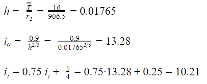
There is a significant difference between the B31.3 SIFs obtained from the hand calculation and the NozzlePro Output: 10.21 vs 8.29 for Inplane and 13.28 vs 10.79 for Outplane.
Earlier that it was mentioned how little user input was required. When no user input is required it often means that the software has to make certain assumptions regarding certain parameters. In this case the default software setting is to calculate the SIFs for the branch (as opposed to the header). To do this calculation for the header it is necessary to check the following box under “Options” and rerun the model.

The NozzlePro-calculated B31.3 SIFs now exactly match the hand calculated values. What should also be noted is how much lower the FEA-calculated SIFs are than those from B31.3 for header.

Note that for the B31.1 and WRC 329 methods there was no difference between the SIFs when the cylinder header option was selected. This gives a clue as to why selection of “header” makes such a difference for the B31.3 SIFs…. How B31.3 treats a reducing tee fitting. This is a slightly controversial aspect of B31.3 and has been pointed out by piping stress experts – readers wanting more on this topic can refer to p116-117 of Peng’s classic text “Pipe Stress Engineering” or the article here on this site.
The applicable section of B31.3 is 319.4.4 equation (20) which requires that an effective section modulus Ze of the branch be used
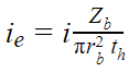
What NozzlePro is doing is calculating an equivalent stress intensification factor ie as recommended by Peng so that the calculated SIF should be used with the actual branch section modulus Zb:
This is as stated in the PRGik Manual. The subscript r represents “run” which is the “header”:
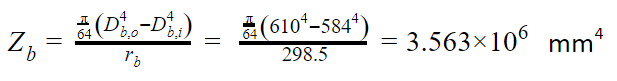
Actual section modulus of branch Zb:
Effective section modulus Ze with Ts = th = 16 mm
Thus, the software is correcting the SIF in order that it can be used with actual as opposed to effective section modulus for the branch SIFs and give the same stress as what would be obtained if the effective section modulus was used.
The calculated SIFs are multiplied by the ratio of Zb/Ze = 3.563 / 4.479 = 0.796
ii = 10.21*0.796 = 8.17
io = 13.28 * 0.796 = 10.62
These values differ slightly to those given by the software (8.29, 10.79). This is because the software calculates the section modulus using the approximate formula of πr2t with thickness t equal to the branch thickness 13 mm, this the ratio Zb/Ze using the approximate method would be 13/16 = 0.813
ii = 10.21*0.813 = 8.30
io = 13.28 * 0.813 = 10.80
These are the same values as calculated by NozzlePro for the branch with the minor discrepancy 0.01 probably due to rounding errors.
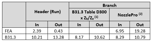
A summary of the results is provided in the table below. It is worth noting that the branch outplane SIFs calculated by FEA are nearly twice that of the B31.3 Table D300 values – i.e. the out-of-plane branch stress calculated using Table D300 methods is non-conservative for this particular tee. At the same time the FEA calculated SIFs for the header are way lower than the B31.3 values. Table D300 has come under scrutiny recently and a number of articles have been published to demonstrate its shortcomings. It is expected that the 2020 edition of B31.3 will remove Table D300 and refer to B31J.
- Recommended by Peng using the exact value for Zb (3.563 x 106 mm4)
- Uses approximate method (πrt2) to calculate Zb (3.639 x 106 mm4) which results in a marginally higher value
Summary
- Models can be developed and run quickly in NozzlePro with minimal user input
- Only 7 use inputs were required to create and run a finite element model of an unreinforced tee
- Users should be aware that for any required information not explicitly entered by the user, the software is making an assumption or using a default value or setting!!
- The NozzlePro default setting is to calculate the branch (as opposed to header) SIFs
- In reporting the branch SIFs NozzlePro adjusts the SIFs so that they can be used with the actual section modulus of the branch – as opposed to the code requirement that it be used with the effective section modulus as required by B31.3. This allows for an apples-to-apples comparison with the other SIFs calculated by other methods (FEA, B31.1, WRC 329)
- B31.3 treatment of reducing branch connections is slightly controversial
- B31.3 Table D300 branch SIFs are generally regarded as being inaccurate and are expected to be replaced in the 2020 edition of B31.3 by B31J.
A lot of aspects have not been covered – in particular the use of the SIFs. In addition, the software provided allowable primary and secondary loads which were not discussed. These will be covered in future articles.

Robert has over 15 years’ experience in the mechanical engineering industry with proven expertise in mechanical and piping design. His most recent role was Lead Piping Engineer for INPEX on the Ichthys LNG Plant. Previously, he served as the client technical authority for the Chevron Wheatstone Downstream Project for all LNG plant piping and onshore pipeline, providing technical support on design, construction and commissioning.