
Quick summary
This article may pique your curiosity if you’re interested in the finer details of pipe stress analysis, but if you’d rather just get the overall takeaway –
- Sustained bending stresses in ASME B31.3 2016 calculations are underpredicted at some branches
- As long as the stress analyst remembers to split the branch pipe model at the shell intersect location, this anomaly will not catch them out
- The recently revised ASME B31J 2017 provides a more sophisticated method of calculating branch stresses which can also circumvent this issue
- Safety factors and the use of good design practice should mean that this issue rarely causes problems in the field if overlooked
Read on if you’d like to get into the whys and wherefores of the matter.
Recap of issue
The earlier post Non-conservative sustained stress covers the issue in more depth. Earlier editions of ASME B31.3 were unclear about how exactly to calculate sustained bending stress at branches, leaving the formula open to interpretation. In certain software such as CAESAR II, there was potential for under-estimating the sustained bending stress at reducing branches due to an effective ‘cancelling out’ of stress intensification factor (SIF) and the use of the 0.75 multiplier for sustained moment index.
Why not submit a code query to the B31.3 committee?
Indeed – I submitted a request in 2015 (Interpretation Record 15-2510), based on the B31.3 2014 edition. This was an interesting experience, being my first encounter with the committee, and could be a whole story for another day. I no longer have a copy of the wording but suffice to say, there was no published response to the query. The Code method is now clearly defined and I’d have to describe it as an own-goal (or at least a penalty kick 😉 ).
B31.3 2016 Edition Gets Specific
The latest edition of the code (released January 2017) gives clear guidance on sustained stress calculation. As a result, the under-prediction of sustained bending stress at branches is spelled out in black and white. The only exception (to the non-conservative method) is for cases where experimental results are being used.
Improvement for experimental or analytical results
B31.3 2016, Section 320.2 Stress due to Sustained Loads
Equations for the stress due to sustained bending moments, 
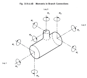
For branch (Leg 3 in Fig. 319.4.4B), use eq. (23b2) only when  or or  is based upon is based upon  , ,  , or , or  taken from Appendix D; when both and are determined by experimental or analytical means, e.g., ASME B31J, use eq. (23b1). taken from Appendix D; when both and are determined by experimental or analytical means, e.g., ASME B31J, use eq. (23b1).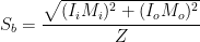 (23b1) (23b1)where is the sustained in-plane moment index. In the absence of more applicable data, is taken as the greater of  or 1.00 is the sustained out-plane moment index. In the absence of more applicable data, is taken as the greater of or 1.00 is the sustained out-plane moment index. In the absence of more applicable data, is taken as the greater of  or 1.00. or 1.00. = sustained section modulus. in eqs. (23b1) and (23c) is described in para. 319.4.4 but is computed in this paragraph using nominal pipe dimensions less allowances; see para. 320.1. = sustained section modulus. in eqs. (23b1) and (23c) is described in para. 319.4.4 but is computed in this paragraph using nominal pipe dimensions less allowances; see para. 320.1. |
The Code now directs that the full branch section modulus be used in conjunction with sustained moment indices determined from experiment or analysis. This is good as it prevents the potentially dangerous misapplication of equivalent section modulus in cases where the sustained index is much less than the stress intensification factor.
Appendix D-based Sustained Moment Indices
When using Appendix D as the basis for the moment index, the designer is directed to use equation 23b2. (Aside – use of the effective section modulus 
 (23b2) (23b2) = sustained effective section modulus. in eq. (23b2) is described in para. 319.4.4, using from Appendix D in = sustained effective section modulus. in eq. (23b2) is described in para. 319.4.4, using from Appendix D in  calculation, but is computed in this paragraph using nominal pipe dimensions less allowances; see para. 320.1. calculation, but is computed in this paragraph using nominal pipe dimensions less allowances; see para. 320.1. |
B31.3 is now specific about the calculation of sustained bending stress at branches. The sustained effective section modulus 

It seems odd that this should be the intent of the Code, particularly as both the sister code ASME B31.1 and the Pengs’ Pipe Stress Engineering text take another point of view – that the sustained moment index should be used to calculate
What is the effective section modulus all about anyway?
If we think of the calculated stress as being in the header pipe local to the branch, we can grasp the meaning more easily. In the chart below, the orange line represents the intensified bending stress at the intersection divided by the unintensified stress calculated using the branch pipe modulus. Starting at the right hand side of the chart, this ratio is rather high because the header thickness is low in this region.
The effective section modulus for this calculation is based on the branch diameter together with the header wall thickness (
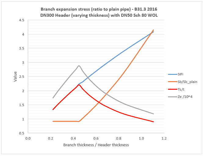
Moving left in the chart, as the header thickness increases relative to the branch, the calculated stress reduces (due to both an increase in 


Sustained effective section modulus
Repeating for sustained stress, the Code says to calculate 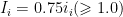
Also shown in the chart are values for a ‘corrected’ formula of 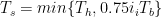
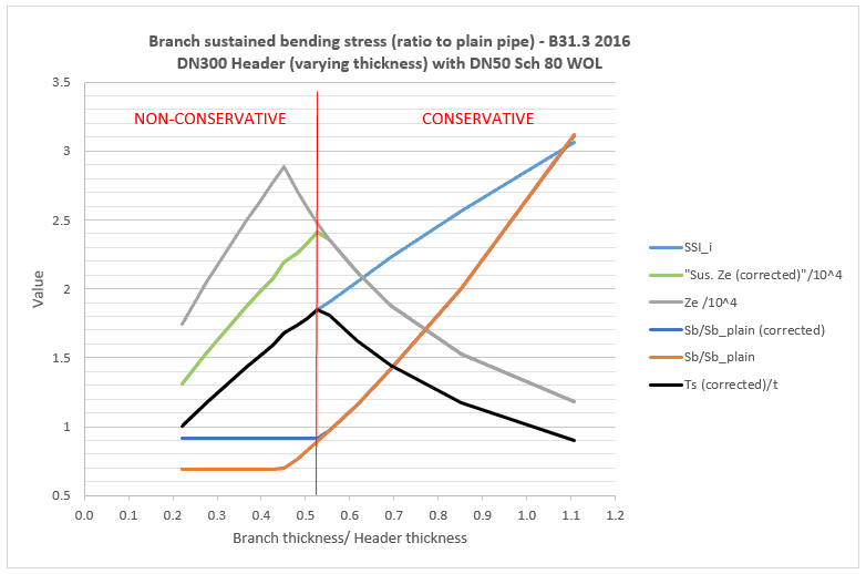
Underestimating the bending stress by around 30% is unfortunate, but you would be unlikely to experience a failure in the field unless something else had gone wrong (such as underestimated weight, poor supporting or high corrosion). Nevertheless, to ensure that you don’t get caught out, I’d advise breaking the branch pipe element at the shell intersection location as shown below. You can see in the pipe stress program screenshot that the stress is higher at the shell intersection than at the centreline intersection (as indicated by the colouring).
What about the centre-offset?
When the header is large relative to the branch, the bending moment at the shell intersection will be somewhat less than at the centreline intersection. This goes some way to reducing the impact of the non-conservative calculation. It’s also quite common for stress analysts to split the branch pipe into a rigid element from centreline to header wall location, and another pipe continuing from there. The analyst then manually enters appropriate SIF and Index values at the shell intersection on the branch pipe. In this case the sustained stress anomaly doesn’t occur – in fact the pendulum swings back the other way towards over-conservatism. This is because the stress program doesn’t know that the intersection is a reducing branch anymore, and the effective modulus calculation is not employed (as an aside, the program also can’t tell the difference between in-plane and out-plane oriented loads – so it must take the higher of the in-plane and out-plane SIF’s).
Another way to model the centre-offset in pipe stress software is to use an ‘offset’ feature, whereby the geometry and intersection type are retained but the length of the branch is modified for calculation purposes. This method retains the effective section modulus but is still prone to the non-conservative sustained stress calculation unless the branch element is split at the shell. This method may also ignore the radial thermal expansion of the header.
Comparison to ASME B31J-2017
This long-awaited update to B31J brings a raft of new equations for piping flexibility and stress intensification factors. Essentially it provides a modern re-write of the 50-plus year old Appendix D. Importantly the branch SIF is no longer taken to be the same as the header SIF at intersections – this aspect has long been a failing of classic methods. Also of note is that the ‘effective section modulus’ is not used with this method. With all the confusion that the effective modulus concept has caused over the years and is evidently still causing, this is a sensible and welcome approach. It also provides new guidance on how to calculate the sustained stress index with increased sophistication over the current ‘0.75 times SIF’ rule. The B31J approach, if adopted, should bring an end to the non-conservatism inherent in the current Code method.
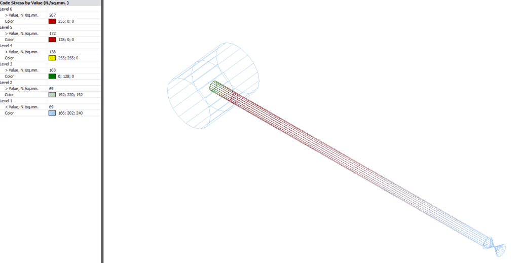
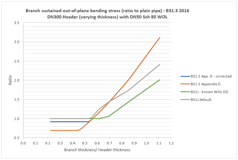
The following chart provides a comparison of the sustained bending stresses calculated via B31.3 Appendix D and ASME B31J. It’s evident that for thicker header pipe (the left hand side of the chart), calculated branch stresses are the same as for plain pipe. To the right of the chart, stresses are fairly similar to Appendix D although less conservative.
Calculation notes
- B31J considers the bending stress at the shell (for d/D<=0.5) instead of the centreline intersection. This has not been accounted for above, but tends to reduce bending moments
- Calculations are shown for both the case where the weldolet outer diameter is unknown (B31J default) and with a known outer diameter (based on Bonney Forge)
- B31J gives a method to calculated sustained stress index for certain branch types, but omits others including weldolets (see ASME B31J-2017 Table 1-1 General Notes (d)). This appears to be an unintentional oversight [Edit – errata to ASME B31J 11-9-2017 now corrects this oversight]. The method in General Note (d) has been used here and results have been cross-checked against PRG’s B31J translator for CAESAR II.
Other Codes
This is a far from thorough investigation, but the apparent status of some other Codes with respect to under-prediction of sustained branch stresses is listed below.
Code treatment of sustained branch bending stress:
| Conservative | Non-conservative |
|---|---|
| B31.1 | B31.3 |
| B31.4 | EN13480-3 |
| B31.8 |
Conclusion
Sustained bending stresses in ASME B31.3 2016 calculations are underpredicted at some branches. As long as the stress analyst knows & remembers to split the branch pipe model at the shell intersect location, this anomaly will not catch them out. The recently revised ASME B31J provides a more sophisticated method of calculating branch stresses which can also circumvent this issue.
Martin helps clients keep on top of their pressure piping and equipment integrity issues via stress analysis, FEA and fitness for service. He is the author of various articles, an ASME paper and software including the Salad post-processor for CAESAR II and web apps on this site. In a former life he played whizzbang lead guitar, but now he just plays old albums..