Assessing fitness for service of pipe fittings is tricky. Whilst we’d encourage you to assess them carefully, what about when you just want to know if you should expend the effort to do more detailed analysis or FEA ? Here is a simple approach that can sometimes be employed when you need a first pass answer.
It’s important to remember that piping components such as tees, elbows and reducers usually need to have wall thicknesses greater than their nominal thickness within the body of the fitting, so that the basic pipe wall thickness calc doesn’t apply directly. The nominal thickness refers only to the thickness at welding ends of the fitting.
What we specify with fittings is really the thickness of the matching pipe. The fitting then needs to at least equal the pressure rating of pipe with that thickness (calculated using the fitting allowable stress), and to have suitable end preparation to be welded to that pipe. What happens within the body of the fitting is largely unspecified, however the manufacturer would generally need to increase wall thickness in parts of the fitting in order to meet the pressure rating (see ASME B16.9 Sections 2.1 and 2.2). The manufacturer could even use a reduced thickness in parts of some fittings, so as to produce an economical design while still meeting the pressure rating requirements. For instance, an elbow may have reduced thickness on its extrados as calculated in ASME B16.49 or B31.3. However, the amount of wall thickness reduction is limited by the tolerances in B16.9 – the minimum thickness (for seamless and welded fittings) is 87.5% of nominal unless otherwise specified.
Apply the logic from pipe specs with corrosion allowance
If we think about most piping specifications for a moment, these have the same corrosion allowance for the pipe and all components; nominal wall thickness is typically selected based on the calculated minimum required pipe thickness plus corrosion and mill tolerance. Therefore if a given amount of wall loss is acceptable for a particular schedule of pipe, it is implied to be acceptable for the matching fitting.
Accepting this premise for now (see footnote for more detail), fittings can be treated as equivalent straight pipe, with remaining wall thickness (RWT) equal to the nominal wall thickness of the pipe minus mill tolerance minus the measured corrosion loss in the fitting (don’t use the measured RWT in the fitting directly for calculation). The allowable stress for calculation should be that of the fitting. For reducing fittings it is recommended to assess with both diameter and wall thickness combinations (for defects located within the transition region). The mill tolerance of seamless or welded fittings is normally 12.5% (refer ASME B16.9 Table 13). It’s quite conservative to use this for calculation but difficult to justify a lower figure unless it has been specified when purchasing the fitting.
Inspection limitations
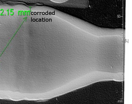
Under this approach, the amount of wall loss must be quantified – for instance by pit gauge or by comparison to an appropriate un-corroded location. There are limitations to the inspection process, e.g. for large defects on components it may not be possible to get a good representation of un-corroded thickness, or it may not be feasible to give an accurate pit gauge reading on a sharp curve such as the transition region of a welding tee. On a large plant you may be able to find another nearly identical fitting in good condition for comparison, or perhaps even an un-corroded region located symmetrically on the fitting (e.g. on a concentric reducer or welding tee).
Examples
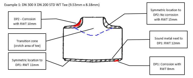
DP1: Check as equivalent pipe with OD323.9 with RWT= 0.875*9.5-(max(11,12)-8) = 4.3mm (minus any future corrosion allowance (FCA))
DP2: Check using OD 323.9mm with RWT=0.875*9.5-(15-10)= 3.3mm (minus FCA); and also using OD 219.1mm with RWT = 0.875*8.18-(15-10) = 2.16mm. The hard minimum thickness limit of 1.3mm on piping (per API 579 (2016) Table 4.4) would be checked against actual RWT = 10mm minus FCA.
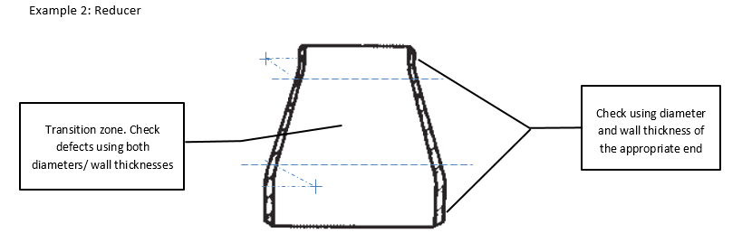
Note that it’s not intended to use the estimated local diameter for checking a defect in the transition zone of a reducer when using this simplified method. By checking using both diameters we are just ensuring that the governing corrosion margin is captured.
Footnote and caveats – treating a fitting as an ‘equivalent’ straight pipe
The required pressure thickness in the body of the fitting is some multiple ‘k’ of the thickness for a pipe of equivalent diameter. Assuming that pressure capacity is proportional to component thickness, the allowable corrosion permitted within the component is in the same proportion ‘k’ to that of matching pipe. As long as k > 1 it is conservative to assume k =1 and to assess as a straight pipe with RWT equal to the nominal wall thickness of the pipe minus mill tolerance minus the measured corrosion loss in the fitting. (Note that the extrados of an elbow has k <1 and should not be assessed in this way – use the code formula instead).
A fabricated tee is not considered a ‘fitting’. There is no requirement that the intersection must match the full pressure rating of attached pipe – it only needs to meet the design pressure of its particular piping specification. Therefore these can sometimes be the governing (lowest rated) pressure component in the pipe class. They should be checked using branch reinforcement rules if the pipe specification corrosion allowance is exceeded.
Integrally reinforced fittings such as weldolets do need to meet the full rating of attached pipe, although there is no guarantee that area-replacement rules will be met after severe corrosion (e.g. the reinforcement area can be attacked in two dimensions and the branch internal diameter can increase with internal corrosion). Therefore it would be recommended to perform area replacement checks on these.
High longitudinal stresses can also be present at pipe fittings, for instance due to thermal expansion or occasional loads. It’s always wise to have someone versed in pipe stress analysis to review the defect location and advise whether a pipe stress check should be carried out.
Martin helps clients keep on top of their pressure piping and equipment integrity issues via stress analysis, FEA and fitness for service. He is the author of various articles, an ASME paper and software including the Salad post-processor for CAESAR II and web apps on this site. In a former life he played whizzbang lead guitar, but now he just plays old albums..