I would like to highlight an issue in ASME B31.3 that’s been sitting there underneath most of our noses for several years. Depending on your interpretation of the Code (or that of your pipe stress software) this can result in significant under-prediction of sustained and occasional bending and torsional stresses at reducing intersections. [Edit March 2017: this article is based on B31.3 2014 and earlier. It still applies generally for B31.3 2016, however a new article will be published shortly to address changes]
Background
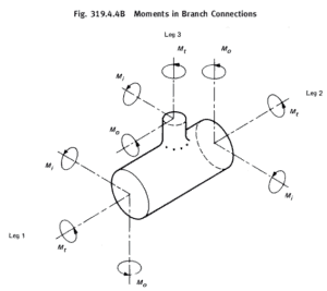
The sustained bending stress for any element is calculated in equation 23b as

is the sustained in-plane moment index. In the absence of more applicable data,
or 1.00
is the sustained out-plane moment index. In the absence of more applicable data,
or 1.00.
are the in-plane / out-plane stress intensification factors for the intersection
= sustained section modulus.
The Code wording is quite vague here, as para 319.4.4 is written for displacement stresses and contains both formulae including the section modulus 
For (the branch end of) reducing branches the displacement bending stress in para 319.4.4 is calculated as


Another way to express this is as follows, assuming the moment is all in-plane for now:


Now applying this approach for sustained or occasional stresses, the question arises for reducing branches as to whether the plain section modulus should be used or the effective section modulus ? Certainly the Code formula only uses the symbol 
Starting again from equation 23b and assuming all in-plane sustained bending moments on a reducing branch:

Taking 

This is clearly only 75% of what the sustained stress should be for the branch pipe. In fact, the simplified thin wall approximation used for
If the moment is all out-plane:

Most intersections in B31.3 Appendix D have 


Example
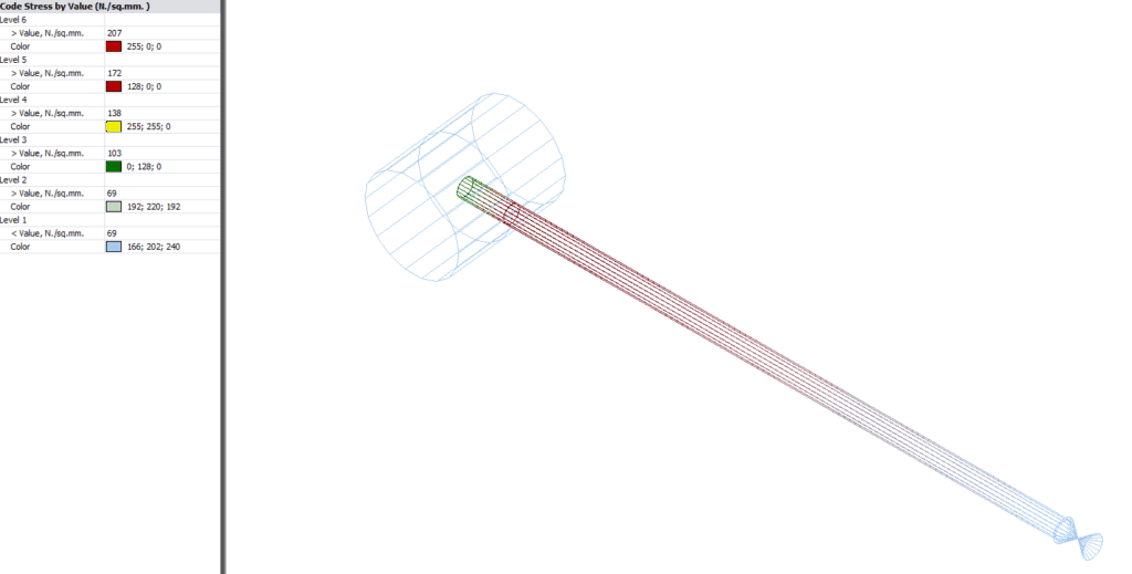
Intersection: DN300 x 50 Sch 40 weldolet (no corrosion).
In the image below from CAESAR II, the sustained stress is clearly lower (green) at the centreline intersection point than at the shell. This higher stress could easily have been missed if the additional node had not been modelled at the header shell location.
Code Interpretation
For the B31.3 sustained stress calculation, I believe that the Code should be interpreted either as not requiring the use of the effective modulus for sustained stress calculations, or that the stress index
This topic is hardly unknown, even being discussed in the excellent “Pipe Stress Engineering” by LC & TL Peng (Section 4.5.1). Their recommended treatment for the sustained effective section modulus is based on the ASME B31.1 approach. The use of 
Use of Stress Index from FEA or Testing
If stress index values are calculated by other means such as B31.J, with an index less than
Practical implications
Analysts often don’t bother to split a branch element at the wall to check the stress there, because they believe rightly or wrongly that the stress at the intersection is always higher. Users should check whether their pipe stress software is prone to this calculation anomaly under B31.3, and if so, they must remember to split the branch pipe and check the stress at the location immediately before the shell intersection, as the Code sustained stress there may well be higher than at the centreline intersection. Alternatively the software may be configured to use the full SIF for sustained stress calculations.
Code Editions
The use of the sustained stress index came about in the 2010 edition of the ASME B31.3. However the option to use
Other Codes – B31.1/4/8 and EN13480
As referred to previously, ASME B31.1 does not suffer from this ambiguity and correctly specifies two different effective modulus formulae for sustained and displacement stresses.
Codes B31.4 & B31.8 are also immune to this issue as they do not use an effective section modulus for reducing branches.
EN13480 does use an effective modulus and at first appearance could be susceptible to this issue, however I have not done any further investigation into this Code as yet.
Martin helps clients keep on top of their pressure piping and equipment integrity issues via stress analysis, FEA and fitness for service. He is the author of various articles, an ASME paper and software including the Salad post-processor for CAESAR II and web apps on this site. In a former life he played whizzbang lead guitar, but now he just plays old albums..