There are many ways to go about supporting pipe, from putting it straight on steel to sophisticated sliding shoe designs. Too often, this aspect of piping design is not given enough thought, resulting in problems later on in the life of a facility. Early on in detail design, the responsible party should prepare a flow-chart specifying the intended pipe support selection for each application.
This article is geared mainly towards uninsulated carbon steel piping and the problem of corrosion at the contact point. The major issues are covered in dot-point form with further explanation as required. If you prefer to skip to the end, you will find a summary of the better solutions and a discussion of my own preference.
Pipe direct on steel
- Coating breaks down due to abrasion
- Can trap moisture under pipe leading to further coating breakdown and crevice corrosion
- Can lead to dangerous wall loss at pressure boundary
- Corrosion of underlying beam
- Corrosion product can eventually cause jacking up of pipe
- Can result in galvanic action for dissimilar material contact
- Fluid temperature can affect support steel
Metallic wear pad on pipe
- Relatively expensive
- Subject to ingress of moist air through vent hole. Vent hole is better omitted.*
- Can’t inspect pipe under wear pad
- Prevents wear of pressure boundary (and reinforces against heavy load)
- Corrosion mechanism still occurs which can lead to jacking up
- Should not be used on lines subject to acoustic fatigue
- Should be attached before PWHT
- Should have rounded corners
* ASME B31.3 requires the use of vent holes at branch connection reinforcing pads. As supports do not penetrate the pressure boundary, a vent hole is not required. The welder must take care to avoid pressure build-up due to hot gases while completing the weld. If a vent hole is used, it should be seal welded.
Stainless wear strip on steel
- Protects stainless steel pipe from contamination
- Can cause galvanic action on beam once a small area of coating is damaged
Small diameter round bar on steel
- Prevents or eliminates water pooling under pipe
- Induces high local stress which can lead to coating damage and pipe deformation
- Abrasive to pipe leading to coating breakdown, wear and corrosion
Welded Shoe
- Welded shoe is a good option under corrosive conditions, as it does not trap moisture in contact with the pressure boundary
- Expensive
- Welded shoes cannot be relocated in the field
- Reduces effect of fluid temperature on support steel
- Guides, stops and hold-downs can be more easily installed and have a lower footprint
- Should not be used on lines subject to acoustic fatigue
- Should be attached before PWHT
While shoes do cause abrasion to the underlying beam, the amount of corrosion experienced at the interface is often less than for a pipe directly on beam. This is perhaps because water does not get drawn in to the contact point so easily.
Clamped Shoe
- Clamped shoes transfer crevice corrosion back to the pipe contact point
- Sometimes slide relative to pipe
- Shoe may rotate under heavy guide load and not provide the desired restraint
- Sometimes lose nuts and bolts
- Expensive
- Reduces effect of fluid temperature on support steel
The usual approach to reduce corrosion at the clamp contact point is to line the clamp with rubber liner (Tico clip strip) or more recent half-round composite inserts (I-rod, Lift-off Pipe). The advantage of using some sort of liner is in preventing damage to coating during bolt-up. However there is still the potential of trapped moisture, which could be addressed by using an immersion-grade coating at these locations.
Non-metallic Isolation pad on pipe
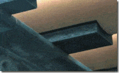
These products are offered by vendors including Advanced Piping Products, AAA Technologies & Specialties and Torgy. The key benefit of this design (like a pipe shoe), is that friction between the pipe and sliding surface is eliminated. Vendors claim extensive use in offshore and LNG facilities in USA, Africa & Brazil. Salient points include:
- May be subject to moisture ingress if not properly sealed around edges
- Could experience disbonding
- Cannot visually inspect the pipe under the pad
- Range of temperatures limited by glue and pad material
- Good for ambient stainless steel piping as protection against galvanic action between pipe and steel.
Full encirclement FRP wrap
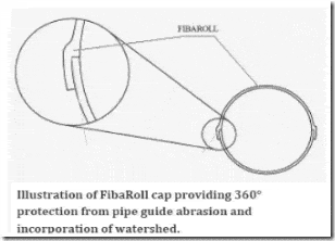
Full encirclement wraps are available from vendors including Clockspring and FibaRoll.
- Full encirclement design is expected to be less prone to moisture ingress and disbonding
- Can be used under hanger clamps and clamped shoes to prevent crevice corrosion
- Upper temperature limited to circa 120°C
- Possibility of cracking under heavy load

The wrap can be also be applied as a hat over an existing part-round isolation pad under the pipe:
The wrap can be tailored to go around small bore fittings. This may potentially open up a moisture ingress path.
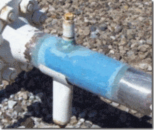
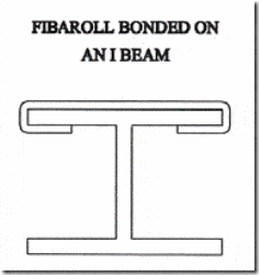
Vendors also recommend applying the product to the underlying support steel to minimise abrasion.
Non-metallic Isolation pad on steel
- Used in numerous facilities
- Materials used include Tufnol, Tico, PTFE, Fabreeka, ASEPlas and FibaRoll.
- May experience disbonding but can be screwed down, or in the case of FibaRoll and equivalents (vinyl esters), wrapped around flange
- May indent or crush
- Does not eliminate minor water pooling or dirt entrapment under pipe, which leads to coating breakdown and corrosion. This is exacerbated if the pad is significantly indented.
- The coating could be upgraded to a submersed type system to extend the time until breakdown. This would add expense to the process, but it could be applied at pipe support locations only.
For minimisation of indentation, high compressive strength and young’s modulus are necessary. Plastic composite products Tufnol, FibaRoll and ASEPlas Grade 1010 are far stronger and stiffer than the elastomeric materials. PTFE falls somewhere between the elastomeric and the plastic products. ASEPlas 1010 has a greater temperature range, -196°C to 160°C compared to FibaRoll & Tufnol which are approximately -40 to 120°C (in fact ASEPlas is intended as a thermal insulator for cryogenic supports).
Half-round thermo-plastic on steel
- Supplied either as u-bolt base or as strips for beam dressing
- Reduces or eliminates water pooling under pipe.
- May experience disbonding (but should be mechanically attached)
- May indent or crush under heavy load
- May cause torsional rotation of beam if only one strip is used (2 or 3 can be used to distribute the load either side of the web)
- Pipe experiences relatively concentrated load which might cause coating damage in some cases, or indentation of thin wall pipe.
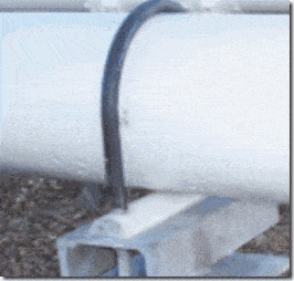
The most prominent brand, I-rod, provides stated load capacities which are adequate for most situations. The material is very stiff which is necessary to avoid significant indentation. Temperature range is -40°C to 170°C using the HT grade. The product has more than twenty five years of usage history in Gulf of Mexico. The vendor has a case study showing long-term performance of the support on their website.
Lift-Off pipe support
Lift-off Pipe is a new entrant to the pipe support market. It has several clever designs having multiple contacts with the pipe rather than point-contact. This reduces localised stress on the coating while minimising water retention via drainage channels.
The supports are supplied in various plastic or composite grades. The standard plastic material used is very hard, to reduce deformation. It can incorporate a layer of molybdenum disulphide to reduce coefficient of friction to 0.1.
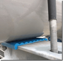
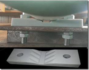
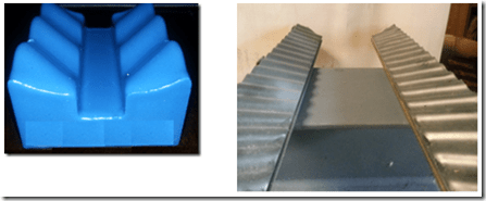
The LOV/ LOB designs do not appear to have a lot of room for lateral movement, and make the pipe ride-up a little as it moves laterally. That said, lateral movement is usually low for most locations in a piping system. Perhaps the main concern would be the apparent reliance on glue to keep the LOV/ LOB supports in position – if the pipe was to squeeze them out of place it could drop some distance.
Summary Table
The following table summarises the better options for uninsulated pipe supports –
| Solution | Pros | Cons |
| Welded shoe |
|
|
| Clamped shoe |
|
|
| Composite wrap |
|
|
| Non-metallic half-round strip |
|
|
| Isolation pad on beam |
|
|
| Isolation pad on pipe |
|
|
| Lift-off Pipe Supports |
|
|
My own preference
As mentioned earlier there should be a flowchart to guide pipe support selection for each application, there is no one solution for all situations. But for ambient and relatively low temperature carbon steel piping (which forms the bulk of many facilities), what is the ideal solution ?
Welded shoes are the ‘best’ solution in my opinion but of course they are expensive. (Nb. welds should extend the full length of attachment plates rather than using stitch welds, which are prone to crevice corrosion). I have left welded wear pads out of the table, but these could be considered the poor cousin of the welded shoe. Clamped shoes in my opinion are generally more trouble than they are worth due to the various issues listed above.
My second preference is for an economical solution that does not impede visual inspection of the pipe. This narrows the field to isolation pad on beam, I-rod and Lift-off Pipe. The I-rod and Lift-off Pipe rest (LOR) have the advantage of minimising moisture entrapment and are therefore preferable to plain isolation pads. The LOR has more contact points and low-friction impregnation, thereby imparting less contact pressure on the coating, and also has a lugged design to keep it in position. The I-rod on the other hand has a long track record and the vendor even shares results from a 28-year inspection on their website. The I-rod has been my traditional economical choice, but if starting a new project I would conduct a close comparison of both options.
I hesitate to recommend composite supports attached under pipe, and it may be my own lack of knowledge but I am suspect of the glue lasting the distance and moisture ingress. I prefer full encirclement wraps in this regard as they have a larger contact area and do not have horizontal edges for moisture to sit. Their capacity under concentrated line loads should be determined in conjunction with the vendor. These too may be a fairly expensive solution but they do have an advantage over the LOR and I-rod in the elimination of friction and abrasive contact with dirt at the pipe/coating surface.
I would welcome comments from vendors or facility engineers regarding their experience, links to case-studies, educational material or inspection reports showing long-term performance of various designs.
In another article I will look at options for remediating existing pipe support contact points.
Martin helps clients keep on top of their pressure piping and equipment integrity issues via stress analysis, FEA and fitness for service. He is the author of various articles, an ASME paper and software including the Salad post-processor for CAESAR II and web apps on this site. In a former life he played whizzbang lead guitar, but now he just plays old albums..


Hi Martin, very good explanation. I’m wondering what is your opinion about Trunnions. Do you treat Trunnions in the same way of Welded Shoes?, regarding to material compatibility, corrosion, and weld fatigue? It is enough just to keep same material for pipe and the pad, for material compatibility, or all the way to the Trunnion itself? What do you think about the lifecycle of the weld?
Jorge, not exactly. Trunnions are usually made with a closed section (ie a pipe), which can lead to problems such as filling up with water or moisture ingress when the weep-hole seal fails. It is often very difficult or impossible to effectively inspect the pipe or elbow inside the trunnion attachment.
Ways to combat this include making sure the trunnion is free draining and installing an inspection hole in the trunnion.
Some companies prefer to specify a re-pad onto pipe first and then the trunnion to repad. This prevents corrosion but reduces capacity as there is possibility of re-pad flexing away from the pipe wall, its not integral with wall. I would personally prefer to use a thicker wall section of pipe or elbow instead and weld trunnion direct to wall.
If welding only to the pad rather than the wall then the material could change there if differential expansion is not too great.
One approach to improve inspectability is to use an open section (eg structural), this can lead to a high stress spot at corners so I’d be a little wary & try to keep the loads low.
Trunnions are typically worse than a shoe fatigue-wise as they have a longer moment arm. They are best welded full pen, sometimes we see fillet welds used but that’s adding a stress concentration to a high stress area. You can sometimes reduce trunnion length by specifying a pedestal under the trunnion.
Yes, differential expansion is my concern, because trunnions are always done with a cheaper material. I’ve seen situations where pipe is duplex or titanium, a pad then a CS trunnion, in hot lines (50 years lifecycle). Same case, but with shoes, requires shoe of titanium because is directly welded to pipe. Some designers consider the material compatibility but never the fatigue caused by differential expansion, in trunnions.
Thank you for your answer
This paper is related to that topic –
http://proceedings.asmedigitalcollection.asme.org/proceeding.aspx?articleid=1647941
Hi Martin,
I have a query about support selection, why clamped shoes are used instead of welded shoe on coated pipe.
My next query is about Axial stop (or line stop) which one is preferable welded shoe axial stop or clamped shoe axial stop. Can you please provide clarification in this.
Hi Martin,
Thanks for your Explanation about Pipe support article.
Can you please explain about selection criteria of Welded Shoe support and Clamp shoe support.
how to check pipe defirmation in case we are using i rod made of steel .how to check what load is oknso that pioe dont dent or deform.