
Background
When process plants have been in service for a long time or approach their end of life the engineering challenges take a different form. It is more complex than laying out a new plant in a greenfield situation.
This article discusses some important observations of a project the author had been closely associated with where a large diameter piping system of a 42 year old process plant was replaced. The lessons learnt in this example can be beneficial to piping engineers when a similar situation is faced. [Also see the companion article on SIF calculation].
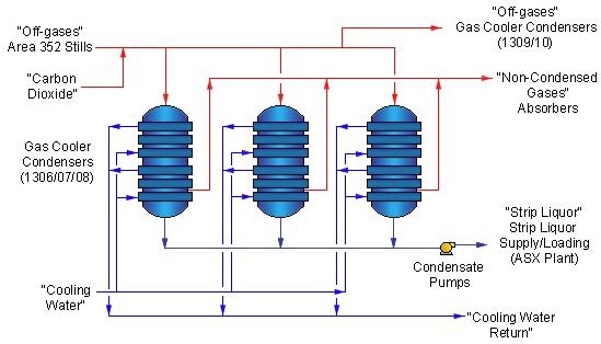
In this example, an inlet header to Gas Cooler Condensers (GCCs) had to be replaced with a suitable design with due consideration to the current state of the plant. A DN1000/ DN600 header feeds the off-gases from the process plant to three GCC vessels where the inlets to the vessels are DN 600. The vessel has been in service since the 1970’s. The existing header is built with sections of carbon steel piping that included uncommon 2x crotch plated lateral tees and 1x crotch plated double tee (cross).
The existing header needs replacement with a suitable design that does not require major piping route changes.
History
Three previous studies proposed major modifications. These were unacceptable as the client did not want to change the basic geometry of the pipework. These studies could not find a way to replace the header with a code complying design without changing the geometry significantly. Major issue was the lack of definition, in ASME B 31.3, for the stress intensification factors (SIFs) of the crotch plated tees and cross fittings used on the header pipework.
These studies assumed conservative SIFs for the fittings which ended up in predicting high stresses at critical intersections. Major configuration changes were required to bring the piping system to comply with the design codes.
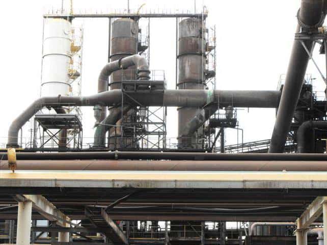
Existing Pipework
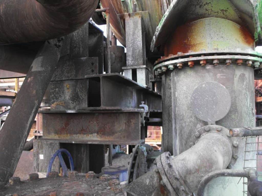
The photo below shows the GCC Gas Inlet Header with the 2x crotch plated lateral tees and the crotch plated cross at the end of the header.
Design Codes
AS 4041 was used for pressure/vacuum containment design of pressure parts while ASME B 31.3 was used for Flexibility Analysis.
New Design Approach
A separate study developed a FEA based method to determine the SIFs of the non standard fittings and a summary of important aspects of the study was captured in a companion article by this author.
A new approach to compute the SIFs of the crotch plated fittings alone was not adequate to meet the redesign objectives of the header replacement. This example and similar situations would require many other aspects and parameters to be considered for an acceptable and economical design.
The Challenge
The challenge was to replace the pipework with the best possible configuration. Therefore the design had to be viewed in different perspectives and they were:
- Loads on vessel nozzles.
- Best material for the service.
- Loads on existing structures and pipe supports.
- Existing piping and structures around the header that could obstruct the thermal movement of the header.
- Constructability
Loads on vessel nozzles
Major consideration in a brownfield replacement piping design would be to establish safe load conditions on the existing equipment nozzles. The current example used CAESAR II piping stress analysis software to establish the maximum safe loads on the GCC vessel nozzles. Analysis considered the corroded piping thickness throughout the existing carbon steel header in order to arrive at a lower bound set of maximum loads. Few iterations considering the corroded and non-corroded vessel nozzles were performed to check sensitivity of the results. This process enabled the study to establish the acceptable loads on vessel nozzles with high confidence.
In the example, the GCCs were 42 year old and glass lined and it was imperative that the new design does not add excessive loads on the glass lined nozzles.
Best Material for the service
The best material for the replacement piping should have:
- Low thermal expansion properties to minimize the thermal growth of the header which intern would minimize the loads on the nozzles.
- Low Young’s modulus so that the stresses caused by the strains are relatively low.
- High yield strength that would allow thinner piping to be used. That will reduce the loads on nozzles and pipe supports.
- Corrosion resistance of the piping material, towards the service will also allow the designer to minimise the thickness of the pipework by reducing or eliminating the corrosion allowance.
Loads on structures and pipe supports
Loads on structures and pipe supports computed from the CAESAR II model for the existing pipework with nominal thicknesses would be an appropriate guide. A few combined load cases will have to be run to determine the acceptable loads.
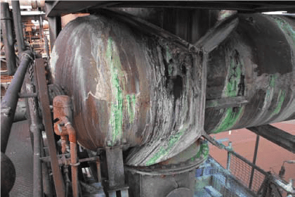
Existing pipework in the vicinity.
Operating companies modify existing plant for operational improvements that often overlook the room for the thermal movement of existing pipework. From author’s experience in brownfield modifications, this step is considered a must and can add immense value to the plant design, at a minor additional redesign and/or demolition effort. Author recommends that every brownfield modification project undertakes this step.
In our example, as evident from the photos, there was piping obstructing the thermal movements of the existing header. The design team, with the concurrence of the client, took the opportunity to modify the existing piping and pipe supports around the GCC inlet header so that the replaced header had the room to move freely.
The use of spring hangers and low friction PTFE pads at critical pipe supports can be used to reduce the lateral loads on structures and pipe supports.
Photo 1 shows the dished end of header in contact with other pipework, restraining free expansion of the header.
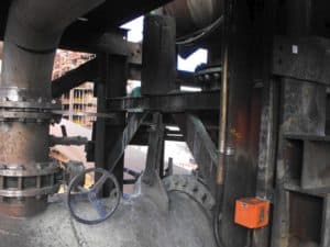
Photo 2 shows the drop rod of the spring hanger moved excessively longitudinally due to thermal movement of the header. As a general rule, the spring rod rotation should be maintained under 3˚.
Photo 3 shows the buildup of clutter in the pipe support steel work over the years.
Design Considerations
When replacing a piping system connected to an existing vessel or any load sensitive equipment, it is required to look for options that could minimize loads on equipment connections. We can achieve this by using a piping system with a (1) lower thickness (2) lower co-efficient of expansion and (3) lower modulus of elasticity.
Lower thickness may be achieved by selecting a corrosion resistant material where the corrosion allowance may be minimized or removed completely from pipe wall thickness calculations, leading to a thinner design wall thickness.
Lower pipe wall thickness can also be achieved by using a material of higher yield strength at the design temperature, requiring a thinner pipe to withstand the design pressure.
However, all these options may not be possible in every situation. Some services will pose limitations to the use of different materials due to specific corrosion characteristics in the fluid streams. Careful judgement by the designer will have to be exercised on a case by case basis.
In our example the existing material was constructed with carbon steel A 53 Gr B, designed with a 3 mm corrosion allowance. Thus, the desirable characteristics of this example would be:
- High corrosion resistance to its service so that the piping design could use a zero corrosion allowance.
- High strength for minimum wall thickness that would reduce the overall weight and minimise the loads on GCC nozzles
- Low coefficient of thermal expansion, preferably as close as possible to the coefficient of thermal expansion of carbon steel or lower. Low coefficient of thermal expansion will translate to lower nozzle loads, for the same thickness and geometry
- Low cost and availability
- Constructability
In consultation with the process and corrosion engineers, it was decided to try the following as material options:
- CS (ASTM A53 Gr B)
- SS (ASTM A312 TP316)
- DSS (SAF2205/UNS31803) and
- Lean Duplex Stainless Steel (LDX2101/UNS S32101)
Comparison of Properties
Material properties considered important in this study were (1) the coefficient of thermal expansion (2) the modulus of elasticity and (3) the yield strength.
The following tables give the coefficient of thermal expansion, modulus of elasticity and yield strength at room temperature (21ºC) of the four different materials considered.
| Temp (ºC) | Coefficient of Thermal Expansion (mm/mm ºC, from 21ºC) x 10-6 | Modulus of Elasticity (MPa) | ||||||
|---|---|---|---|---|---|---|---|---|
| LDX2101 | 316 SS | CS | SAF2205 | LDX2101 | 316SS | CS | SAF2205 | |
| 21 | 12.5 | 16.4 | 10.9 | 12.5 | 200000 | 195000 | 203000 | 195000 |
| 100 | 13.0 | 16.8 | 11.5 | 13.2 | 194000 | 190000 | 198000 | 190000 |
| 200 | 13.5 | 17.2 | 12.2 | 13.6 | 186000 | 183000 | 191000 | 183000 |
| 300 | 13.5 | 17.6 | 12.9 | 14.0 | 180000 | 175000 | 185000 | 175000 |
| Yield Strength at Ambient (MPa) | |||
|---|---|---|---|
| LDX2101 | 316SS | CS | SAF2205 |
| 448 | 207 | 241 | 448 |
Observations from the above tables are:
- LDX2101 has a co-efficient of thermal expansion comparable with carbon steel
- LDX2101 has a much higher yield strength compared to 316SS, carbon steel and similar strength comparable with SAF 2205
In addition to above, LDX2101 has:
- weldability and machinability comparable to that of 316SS
- 5 % Ni compared to TP316SS’s 12% Ni and SAF2205’s 5% Ni, which leads to lower costs compared with TP316SS and SAF2205
- has higher pitting resistance (governing corrosion mechanism) compared to 316SS and SAF2205
- relatively freely available in plate form up to 12mm thickness.
From the discussion above it is evident that LDX2101 (UNS32101) meets most of the desirable requirements in the material to replace the GCC off-gas header.
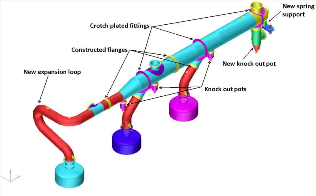
The redesigned piping system was able to meet the established maximum vessel nozzle loads requirement with only a minor expansion loop above the leftmost GCC vessel, as shown in the modified layout plot. System stresses were within ASME B31.3 allowable values.
The pipe support system was designed to provide lateral movement with minimum resistance with the use of carefully selected spring support and PTFE low friction sliding pads.
Construction flanges were added to fabricate the piping in manageable sections, that permitted lifting and maneuvering.
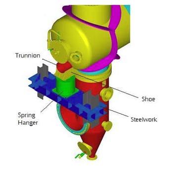
Modified support system included a horizontal trunnion (red) welded on to the dished head and a spring support (green) holding up the trunnion via a shoe (yellow). Spring Can is fixed on to the steelwork (blue) and the spring can move with the structure laterally whilst holding the vertical load. Load plate was provided with a PTFE pad to facilitate sliding and minimizing the transfer of frictional loads to the structure.
Conclusion
By developing a methodology for determining SIFs of crotch plated fittings, selecting the most appropriate material for piping and modifying the design to ensure acceptable loads on equipment connections, replacement of an existing large diameter process piping system yielded a successful outcome.

Nimal Jayaratne
![]()