Background
Some instances in piping stress engineering we come across fittings not defined in ASME B 31.3, due to their sheer size and/or the diameter to thickness (D/t) ratio. Without understanding the stress intensification factors (SIFs) of fittings, flexibility analysis becomes impossible. This discussion is about how a challenge for the determination of SIFs of non standard fittings was overcome in a brownfield situation.
In general any piping tee fitting whose D/t ratio ratio exceeds 100 cannot be assessed using ASME B31.3 SIF rules. Also, ASME code covers only the shapes and sizes which have been through A R C Markl’s fatigue testing programme in the 1950’s.
In this example we look at a complex piping system of a mineral processing plant that included following non standard fittings:
- Crotch plated 45 degree lateral tees
- Crotch plated 90 degree double tees or crosses
The above fittings can have many variants, like equal, unequal, non reinforced, pad reinforced or integrally reinforced. We come across such fittings in existing chemical plants and piping systems which often require flexibility analysis in order to check compliance with design codes. A knowledge of their SIFs is a pre-requisite to flexibility analysis. Piping Engineers have been using empirical rules to get over this difficulty, often leading to uncertain and/or over designed systems.
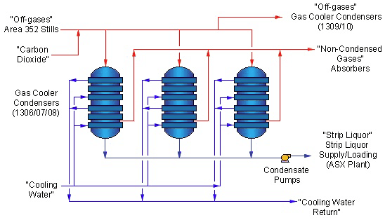
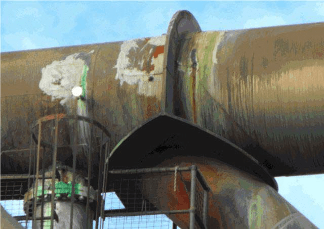
In this example, we discuss a piping system where a Gas Cooler Condensers (GCCs) cool off-gases from a processing plant. This particular piping system has been in service since the 1970’s and remained in service until 2012, albeit in a dilapidated condition that required replacement.
History
Various attempts were made in the past to redesign this piping system but none could proceed to completion as a suitable methodology to assess the SIFs of these non standard fittings was not available.
Three previous studies proposed major modifications. These were unacceptable as they proposed major changes to the geometry of the pipework. Client was insisting on examining options that did not include major geometrical changes to the piping system. Clients argument was that the existing piping system has survived nearly 40 years and piping engineers should be able to find an explanation to this conundrum.
With the increasing acceptance of Finite Element Analysis (FEA) as an analysis tool in industry, it was suggested that an investigation be undertaken to study the use of FEA to investigate the stresses in these fittings and to interpret the results in the light of the design intent of ASME B31.3.
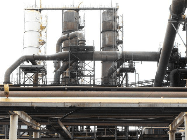
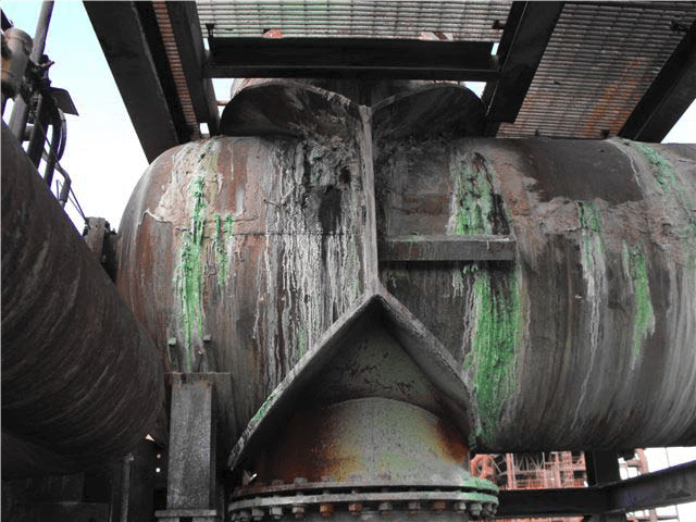
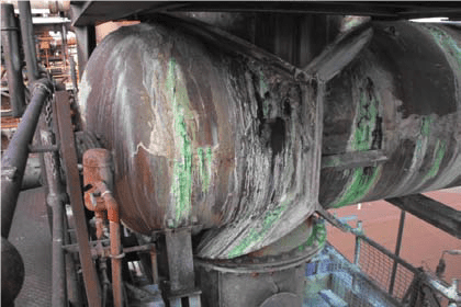
Existing Pipework

These fittings have been used over 50 years in piping/ducting systems and they were around when A. R. C. Markl’s did his testing program in 1950’s. Some crotch plated branch fittings are shown in the Piping Handbook ‘Design of Piping Systems’ published in the 1950’s by M. W. Kellogg Ltd. This handbook was considered an authoritative source of information for the piping engineer of that era. However, these crotch plated branch fittings were not part of Markl’s fatigue testing programme, thus missed out of being part of ASME B 31 series SIF definition.
Markl’s definition of SIF
ASME B31.3 SIFs are based on A R C Markl’s results of a series of fatigue tests carried out in the 1950’s. Let us look at Markl’s definition of SIF closely.
The SIF is a stress raiser that, once applied to the calculated stress range, causes failure in the component at the same number of cycles as a straight pipe with butt welded joints. Markl also determined that commercial girth butt-welds typically resulted in stresses 1.7~2.0 times the stress in the non-welded piping.
As a result, the B31 piping codes have been baselined to include the factor of 2.0 for girth welds.
For ease of application, Markl’s SIF can be defined as:
“SIF = Peak stress due to bending moment within the fitting / 2*stress obtained for straight pipe under same bending moment from a beam-type equation”
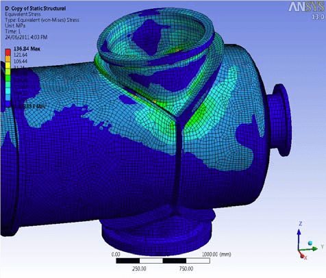
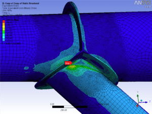
It was recognized that ‘peak stress’ within a fitting can be obtained from an accurate FEA of the fitting.
In this exercise, CAESAR II software was used extensively to compute bending moments at all tee fittings under investigation. Torsional moments & axial forces were not considered as they were not significant. The bending moments were then input into an ANSYS FEA model to generate the peak stress 
Bending stress in a straight pipe was also computed manually using code formulae 
SIF was computed as follows:

Results
Comparison of SIFs Calculation Results: Cross Fitting
Table 1 – Stress Intensification Factors Determined by FEA for the Cross Branch Fitting
| Unreinforced Tee | Pad Reinforced Tee | Crotch Plated Tee | Remarks | |||||||||
| SIFs | SIFs | SIFs | ||||||||||
| iibn | iobn | iitn | iotn | iibn | iobn | iitn | iotn | iibn | iobn | iitn | iotn | |
| 4.9 | 9.85 | 5.92 | 14.09 | – | – | – | – | 2.39 | 3.16 | 2.77 | 3.50 | |
| 2.391 | 3.161 | 2.771 | 3.501 | Used in stress analysis | ||||||||
Legend:
iibn= in plane SIF bottom nozzle; iobn= out of plane SIF bottom nozzle; iitn= in plane SIF top nozzle; iotn= out of plane SIF top nozzle
Notes:
- The SIFs determined for Crotch-Plated cross branch fitting were used for stress analysis.
- Reinforcing pad option was not examined as it was not possible to use reinforcing pads on the cross due to dimensional limitations.
Comparison of SIF Calculation Results: 45 º Lateral Branch
Table 2 – Stress Intensification Factors Determined by FEA for the 45 º Lateral Branch Fitting
| Unreinforced Tee | Pad Reinforced Tee | Crotch Plated Tee | Remarks | |||||||||
| SIFs | SIFs | SIFs | ||||||||||
| iih | ioh | iib | iob | iih | ioh | iib | iob | iih | ioh | iib | iob | |
| 2.90 | 0.71 | 4.97 | 15.86 | 1.74 | 0.58 | 4.93 | 17.35 | 2.13 | 0.60 | 2.86 | 2.63 | |
| 2.131 | 1.01,2 | 2.861 | 2.631 | Used in stress analysis | ||||||||
Legend:
iih =in plane SIF header; ioh =out of plane SIF header; iib =in plane SIF branch; iob =out plane SIF branch;
Notes:
- The SIFs determined from Crotch-Plated lateral branch connection were used for stress analysis.
- Minimum acceptable SIF to ASME B31.3 is 1.0.
Verification
In addition of computing SIFs using ANSYS FEA software, a verification of the results using FESIF (a specialist software from Paulin Research Group) was also carried out on known intersections to demonstrate the validity and the accuracy of the methodology. The following is a typical comparison:
| Plane | B31.3 | ANSYS FEA | FESIF* | % Diff FEA:FESIF |
| Branch in-plane | 4.4 | 5.18 | 5.49 | 5.9% |
| Branch out-plane | 5.5 | 15.59 | 17.47 | 12.1% |
| Header in-plane | 13.21 | 2.87 | 2.67 | -7.0% |
| Header out-plane | 17.29 | 0.69 | 0.68 | -1.0% |
* FESIF with SCFs set to 1
Above confirms the results of FESIF closely resemble the results derived from ANSYS FEA software.
Conclusion
SIFs calculated using the above methodology are acceptable to be used in flexibility analysis in design, in accordance with ASME B31.3.

Nimal Jayaratne
![]()
Good job Nimal.
I really enjoyed working with you in that project.
I remember vividly the SIF calculation.
Congratulations.
Jesus